

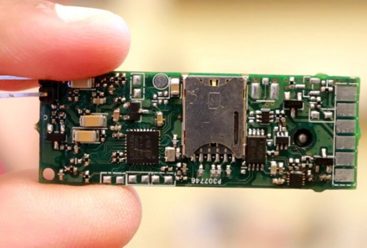
All electronic components nowadays rely on the same base: the printed circuit board. PCBs contain boards made of insulated material, metal coatings and roads that enable the transmission of electricity. From some very simple electronic devices, such as garage door openers, to very complex components present in computers – the printed circuit board is a vital part of each of them. Electrical device failures often occur, and repair requires determining the presence and type of failure on the printed circuit board. While this is by no means an easy task, there is still a way to detect problems that may occur on parts of the PCB. Here’s how to know if PCB components are bad.
Troubleshooting
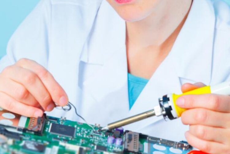
If you suspect that there are defects in the components on the printed circuit board, it will be necessary to examine all the individual parts and conclude what the problem is. Sometimes the cause is obvious and easy to fix, while other types of failures are more complex and, therefore, require more work. Troubleshooting also involves the use of several tools that are of great help during this process. Some of the most important are the signal generator which allows you to assess how the board works and whether there is a problem in the formation and transmission of signals during the operation of the PCB. Another important tool is the oscilloscope, which makes it easier to estimate the waves of an electrical signal and monitor these signals over time. It provides all the data that can be relevant when checking the performance of a PCB and greatly simplifies the whole process.
What is important to note is that if you want to prevent this whole process and reduce the risk of PCB failure, it is a good idea to choose a reliable manufacturer that offers high quality PCBs, such as those you can find at pcbonline.com.
How to check PCB components and determine if they are bad
Step 1: Remove any parts of the device that are blocking access to the printed circuit board
To begin with, it is necessary to disassemble the device in order to reach the board and be able to examine it. Remove the cover and remove any parts that are clipped to the PCB. Usually all electronic parts are connected to the PCB with a few screws. Use a screwdriver to remove them. Dispose of parts of the device that you do not need.
Step 2: Turn off the power source
Before starting the PCB test process, it is necessary to turn off the power source so as not to injure or further damage the PCB. Unplug the power cord and proceed to the test.
Step 3: Check all PCBs within the device
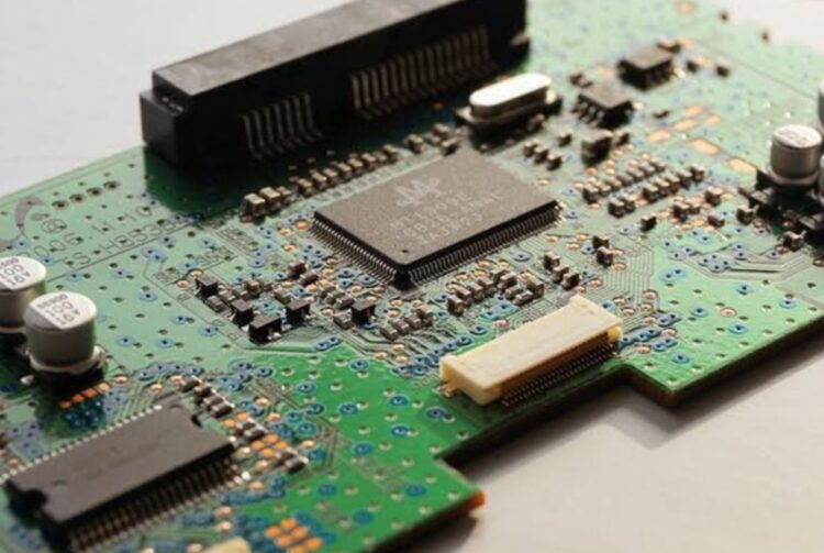
Sometimes electrical devices have only one printed circuit board, but within more complex equipment, several of them can be found. If this is the case with a device that appears to be defective, it is necessary to check that each of the existing PCBs is adequately connected. Sometimes there is no malfunction at all on the board components, the only problem is that the PCB connectors are loosely connected, so there are problems in the operation of the device. Try to push the cards into the slots as much as possible, and then make sure you solve the problem.
Step 4: Check all fuses
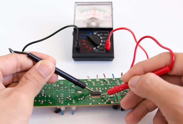
Depending on the material the fuses are made of, you can use different methods to determine if they are working, or if they have failed for some reason. When it comes to glass fuse, you can easily conclude if it has burned out by checking the filament. If the thread is broken somewhere, it will be a sign that the fuse is not working. If it is made of ceramic, you can perform this process using a multimeter.
Step 5: Look for foreign objects
Sometimes the problem is not in the printed circuit board itself, but there is a foreign body that interferes with the work of its components, so keep that in mind. It can be water, a paper clip, or something else. Removing these interferences can lead to the establishment of regular operation of the board and the entire device.
Step 6: Detect any potential physical damage to the PCB
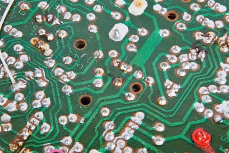
Broken parts of the board, protrusions, wires that are broken or burnt, scratches and all other physical damage to the components can be the cause of failure of the PCB and the device of which this board is an integral part. If something is physically damaged, it is very likely that it is broken and is the cause of the whole problem. Also, if some of the components have melted or changed their color, focus on them, because it is possible that they are the cause of the malfunction. In case you notice some of these signs, it will be necessary to try to fix these problems and decide whether something can be done, or you’ll need to replace the entire board.
Step 7: Use an oscilloscope to get the necessary information
Plug in the PCB and start testing the signal transmission and voltage of each connection with an oscilloscope. Write down all the results and compare them with each other, in order to conclude whether there is an isolated fault or whether the board is generally bad and it is necessary to completely replace it in order to solve the whole problem. With the right tools and a little patience, you will be able to detect a malfunction, and then make a decision on how to fix it.
Conclusion: Most electrical and electronic devices nowadays rely on the use of printed circuit boards, regardless of whether they are very simple devices, or some far more complex ones, such as computers. And also the failures that happen in these devices can often be a consequence of a bad PCB or an isolated failure of one of its components. Although the process of solving the problem in such cases is not always simple, if you follow these instructions, there is a high chance that you will be able to detect the problem and solve it as quickly as possible.


